
Results 11 to 20 of 30
Thread: Yale 101-1/2 comb lock
Hybrid View


-
06-12-16, 10:56 PM #1
 Member
- Join Date
- Oct 2009
- Location
- Cleveland, Ohio USA
- Posts
- 1,444


Here is the lock prior to takedown. As you can see the wheels are well concealed. Offset drive with redundant wheel pack, meaning only one is needed to open the lock. It cannot be set to dual custody.
-
13-12-16, 05:14 AM #2
Member
- Join Date
- Oct 2009
- Location
- Cleveland, Ohio USA
- Posts
- 1,444
Most of my patent copies were right out of the patent books. Not sure why it doesn't come up. Try googling B.F. Klohs and it should come up. Unfortunately the lock is not mine but from a restoration job. Since the lock had to come off the safe anyway, I decided to do this pictorial of the lock.
-
13-10-17, 01:35 AM #3
Member
- Join Date
- Oct 2009
- Location
- Cleveland, Ohio USA
- Posts
- 1,444
Jody, post a picture of the time lock so I can see the position of the mainspring winding disc. Also if you took pictures as you disassembled the time lock post them as well. I am unable to post pictures onthe forum at this time. But to answer your question, yes the mainspring requires a preload to fully retract the bolts. There are other possible causes of your problem, such as are the bolts freely moving in the door bolt holes. Was the slotted pinion gear properly aligned with the mainspring pinion? It has been a couple years since I last worked on one and have to relearn how they work every time. Anyway as long as you are not in a hurry, I am currently cleaning and lubing the movements of a Y-361 and when finished will be checking it for proper operation. As I do this I will photograph the assembly. By then I should be able to post the pictures, but that won't happen real soon.
-
02-11-17, 12:23 AM #4
 Member
- Join Date
- Jan 2016
- Location
- Austin, Texas
- Posts
- 30
Y 361 Spring Motor
Mr. MacQueen,
On my Ely-Norris safe, the trim ring around the Y-361 timelock does not have a cut out or notch around the timelock cover hinge. So there it is impossible to remove the trim ring from around the brass timelock case without taking out the part that holds the watch mechanisms. That gives access to four bolts that secures the case to the safe door. The brass timelock case has to be removed to get the trim ring off. So I did that which expose the locking mechanism.
I did not disassemble the lock works, other than to take off the gear that engages the spring motor. It is keyed so can only go back one way. I put it back with the engraved numbers facing out which is how the gear came off. It has play in it by way of two slots and can rotate about a quarter turn. This seems to be so that when the locking bolts are released then the gear can rotate without having to wind the spring motor. Otherwise the release springs would be fighting against the winding springs. Right??
I think when I removed the part holding the clocks from the brass case, then the spring motor might or must have come unwound some and lost tension. I just cannot remember. I have never removed the spring motor from the case and would not be dumb enough to mess with it. It looks fine and I have sprayed it with WD-40 and then some Remington Gun oil. There seem to be two of them.
Because of the way the time lock case must be removed for the trim ring around it to be removed, I am at a loss to figure out how to put the clocks and case with the spring motor back together. There is no way that I can see to assemble the two together and install as a single unit. The clock mechanism blocks access to the four bolts that secure the base to the safe door.
Here is a picture of the timelock winding disc, but with it detached from the spring motor it can rotate to most any position. The lug on the back has a bevel so that it attaches to the spring motor only in one way.
Hope you can help me.
Jody Sims
-
18-11-17, 07:36 PM #5
Member
- Join Date
- Jan 2016
- Location
- Austin, Texas
- Posts
- 30
Y 361 Spring Motor
Mr. MacQueen,
You pointed me in the right direction and were spot on that the spring motor has to be pre-tensioned. I found this picture I took of the spring motor spring before I removed the time lock case. I stuck a screwdriver in the square hole and wound the spring and held it as I engaged the spring motor square shaft with the pinion and bolted the brass case back in.
My timeclock is working fine now.
Thanks again for the tip.
Jody Sims
-
08-12-16, 12:31 AM #6
Member
- Join Date
- Oct 2009
- Location
- Cleveland, Ohio USA
- Posts
- 1,444
When changing the comb, the outer wheel sections are moved out of engagement from the inner wheel. This is accomplished with a simple turn of the key, but the design of the parts to pull this off is not so simple. A cage surrounding the wheels is center hung similar to the door and crane hinge of the cannonball. This allows for a straight albeit slight in and out movement of the wheel cage as the key is rotated.
-
13-12-16, 05:09 PM #7
Member
- Join Date
- Dec 2009
- Posts
- 1,489
I almost never use Google for patent searches unless it's something the US patent office can't do (such as search older patents by inventor name), or I'm not looking for a US patent.
In this case Google Patents (http://patents.google.com), given 1066629 as the search term, comes up with foreign patent GB1066629A which is for a loading apparatus for a lorry. It does, however, prompt you with other possibilities including US1066629A which is the one in question. Of course the US patent office comes up with the patent of interest given that number.
Is that the difficulty you were having?
-
08-12-16, 12:40 AM #8
Member
- Join Date
- Oct 2009
- Location
- Cleveland, Ohio USA
- Posts
- 1,444
A couple more pics.
-
13-12-16, 09:41 PM #9
Member
- Join Date
- Oct 2009
- Location
- Cleveland, Ohio USA
- Posts
- 1,444
Wylk, I was hoping you might have some input regarding patent searches. Here are pictures showing the bolt retraction connecting linkage. Note however the bolt didn't retract even though the linkage moved into the opening position. To the few of you who are actually studying this post, any ideas as to why this occurred? There will be a little something in your stocking if you get it right.
-
19-07-23, 07:18 PM #10
Member
- Join Date
- Jan 2016
- Location
- Austin, Texas
- Posts
- 30
Yale lock hard to turn
Mr. McQueen,
Thank you for all your help in the past. I haven't been on this site for a while. I have an Ely Norris Cannonball with the Yale dual locks. My problem is the dials have become increasingly harder and harder to turn. Is there a way to lubricate the two combination locks?
Thanks,
Jody Sims


 Reply With Quote
Thread Information
Users Browsing this Thread
There are currently 8 users browsing this thread. (0 members and 8 guests)

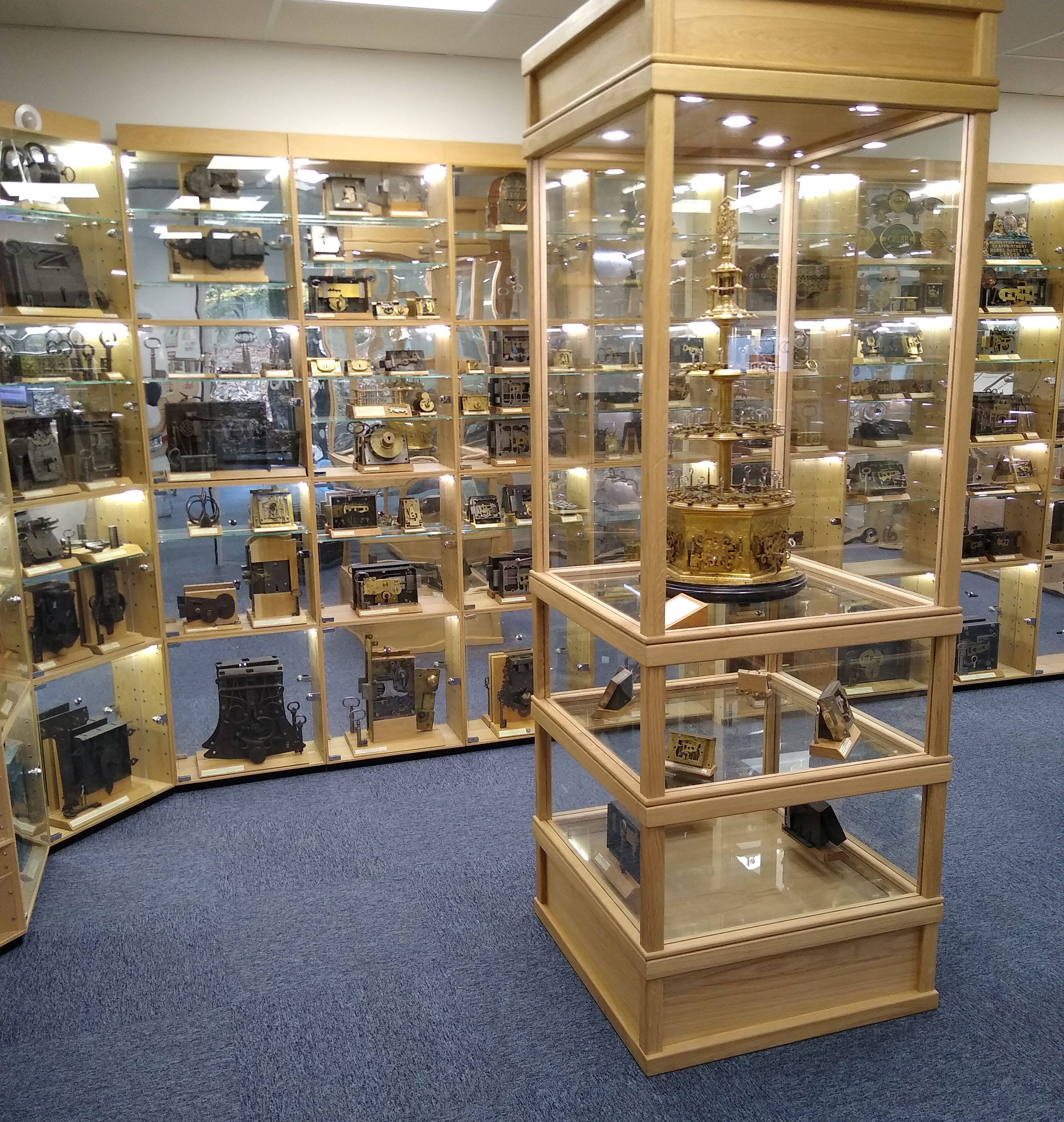


A couple more pictures of this lock which is almost certainly German.
Chubb Bramah key